Coupler
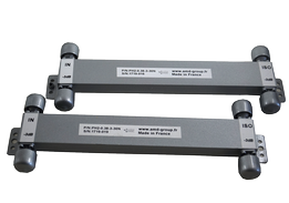
Directional Coupler
A directional coupler is used to sample a portion of an input signal for test and/or monitoring purposes. This “sample” signal is typically of much less power than the original input signal.
The coupling value of a directional coupler defines the difference in power between the input signal and the “sample” signal as it is observed at the coupled port. Pulsar offers a complete line of 6, 10, 11.5, 15, 20, & 30 dB couplers in various package styles covering selected frequency bands up to 18 GHz.
Coupling
The attenuation of a signal injected into the input port as seen at the coupled port.
Coupling Flatness
The maximum variation in the coupling value over a specified frequency range.
Directivity
The
level of output power at the coupled port when a signal is injected
into the unit in the desired direction minus the level of output power
at the coupled port when the same signal is injected in the opposite
direction. In a bi-directional unit, it is the difference in output
power between the two coupled ports as seen from a constant signal in
the same direction.
VSWR
The
VCWR (Voltage Standing Wave Ratio) at any given port (with all other
ports terminated) defines the degree of mismatch between the input
signal and the input port and thus is a measure of the loss of input
signal at that port.
Coupling Loss
Power lost from the input signal due solely to the power transferred to the coupling arm of the devise.
Mainline Loss
The difference in power between the input signal and the output signal. It is the Insertion Loss and Coupling Loss.
Insertion Loss
The loss of unrecoverable power dissipated within the unit.
Coupling value | Coupling Loss (dB) |
6 dB | 1.2 |
| 10 dB | 0.46 |
| 15 dB | 0.14 |
| 20 dB | 0.04 |
| 30 dB | 0.004 |
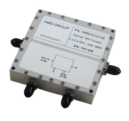
Coupler hybride
90° Hybrids split an input signal into two equal amplitude output signals which are 90° out of phase from each other.
Like in-phase dividers, 90° Hybrids may also be used as a power combiner.


Insertion Loss
Insertion loss is the difference in
power between the input signal and the output signal above the
theoretical split loss of 3.0 dB.
Amplitude Balance
The maximum difference in power level between the output signals.
Phase Balance
The maximum phase difference in degrees between the output signals.
Isolation
The
isolation is used to define the amount of output port to port
crosstalk. It is the level of attenuation of a signal injected into an
output port as seen at the other output port with the input terminated
in 50 ohms.
VSWR
The VSWR
(Voltage Standing Wave Ratio) at any given port (with all other ports
terminated) defines the degree of mismatch between the input signal and
the input port and thus is a measure of the loss of input signal at that
port.

