Systems - AMD GROUP
AMD-GROUP
Analogue Microwaves Design
French Microwaves Design & Product
Systems
Products
We have developed a wide range of matrix switch till 24 inputs and 24 out puts.
Available configuration are Fan-Out 1x1 and Non-blocking.
Those matrix are used to commute N antennas to M receivers and monitoring and controlled by software.
Remote control of matrix could, as optionally defined, be by Ethernet, USB, RS232 or RS485 protocol.
Standard bandwidth : 2-30MHz, 20-3000MHz, DC-18GHz.
- Matrice commutation - Integration - Systems
- Integration Services -Sub-Systems
- Prototyping through to mas production
- Assembly of « key » systems - Rackmounted units, Cabinets, modular unit...
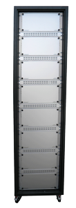
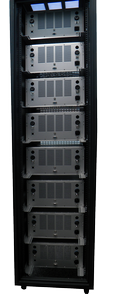
Radio bay for military sector
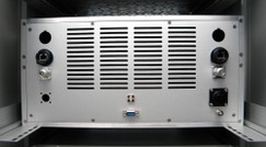
Rack
Matrice de commutation
Over the years, the microwaves research & development of AMD-GROUP has become a privileged partner of french and european industries offices.
In addition, our experience and the flexibilty of our team makes us reactive and considerably reduces our completion times.
- Switch matrix
- Automatic test bench GSM, DCS, UMTS
- Fading simulator to 38 GHz
- Multicoupler
- Radar simulator
- Frenquency convertor
- Spliting rak
- Gain egualyzer
- Microwaves balize 5.8 GHz
- Test generator for TACAN
- RF synthetizer
SWITCH MATRIX
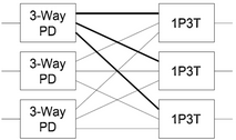
Blocking Matrix
The below schematic shows an example of a 3 X 3 non-blocking matrix. It is built with power dividers on the inputs and switches on the outputs. Each input signal is split to all output switches. This confi guration provides greater switching fl exibility because you can have multiple output ports connected to the same input port at the same time.
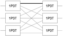
Non-Blocking Matrix
The below schematic shows an example of a 3 X 3 blocking matrix. It is built with switches on both the input ports and output ports. Each output port can only be connected to a single input port. Also, each input port can only be connected to a single output port. This confi guration maximizes the isolation between ports and minimizes the insertion loss of the system.
RADIO TEST SYSTEM
Handover Test System
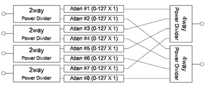
The below schematic shows an example of a standard 4 X 2 handover test system. Every possible path from Antenna to Terminal has its own programmable attenuator. With this configuration the simulation of signal fading can be achieved. With Ethernet and USB control, we can provide you with the remote commands to simplify your test setup such as Handover, Variable Handover, Fade Attenuator, and Pause.
Transceiver Test System
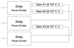
The below schematic shows an example of a standard 3 port transceiver test system. Every possible path from port to port has its own programmable attenuator, so you can simulate changing distance in a network. With this configuration you can vary the attenuation between radios. With Ethernet and USB control, we can provide you with the remote commands to simplify your test setup such as Handover, Variable Handover, Fade Attenuator, and Pause.
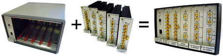
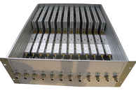
MODULAR CHASSIS TEST SET
Buildup yourself
The SYS14002 and SYS14002-1 modular chassis are capable of hosting respectively 6 and 12 module of 3U 7F.
Those units hold inside a control module to connect the system to a computer by USB or Ethernet protocol.